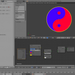
As promised, here’s how I did the talking circles. The material setup is pretty simple – most of the heavy lifting takes place in the script which I’ve included below.
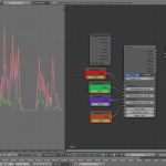
In the node setup, LoFreqInput, MidFreqInput, and HiFreqInput are all driven by an F-Curve baked from the sound file. (Important tip: when baking f-curves from sound, ensure your cursor is at frame 1 – it’ll start baking the sound from wherever the cursor is placed.)
Bake Sound to F-Curves turns the amplitude of a sound file into a series of values from 0.0 to 1.0. It has the following useful parameters:
- Lowest Frequency: Any activity below this sound frequency will be ignored
- Highest Frequency: Any activity above this sound frequency will be ignored.
- Attack time: how long it takes for a stronger signal to register as a change in value – larger attack time means more smoothed out values, shorter attack time means the f-curve responds quicker to changes in amplitude so jitter is more likely
- Release time: how long it takes for a change in signal to tail off – larger release times mean peaks are held for longer, slower release times mean the peaks drop away quicker.
- Threshold: how loud the signal has to be before it registers on the F-Curve.
There’s Accumulate, Additive, Square and Square Threshold as well, but I haven’t played with those yet. Incidentally, you can press Space and type Bake Sound to from the F-Curve view to call the function. 🙂
I went with the default attack/release values when baking all the curves. In the material setup, LoFreqInput was 500.0 high; HiFreqInput was 5000.0 low, and MidFreqInput was everything in between. Amplitude was all frequencies – basically the defaults.
Here’s the relevant bits of the script itself:
shader voiceSpec(
point Po = P,
float Scale = 1.0,
float Offset = 1.0,
float TwitchScale = 1.0,
float LoFreqCarrier = 1.0,
float LoFreqMultiplier = 1.0,
float MidFreqCarrier = 1.0,
float MidFreqMultiplier = 1.0,
float HiFreqCarrier = 1.0,
float HiFreqMultiplier = 1.0,
output color Colour = 0.5,
output float LoFac = 0.0,
output float MidFac = 0.0,
output float HiFac = 0.0,
) {
float Distance = distance(point(0.0,0.0,0.0), P) * Scale;
LoFac = sin(Offset + (Distance * LoFreqMultiplier) + (LoFreqMultiplier * TwitchScale * LoFreqCarrier)) * LoFreqCarrier;
MidFac = sin(Offset + (Distance * MidFreqMultiplier) + (MidFreqMultiplier * TwitchScale * MidFreqCarrier)) * MidFreqCarrier;
HiFac = sin(Offset + (Distance * HiFreqMultiplier) + (HiFreqMultiplier * TwitchScale * HiFreqCarrier)) * HiFreqCarrier;
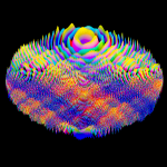
Colour = color(MidFac, HiFac, LoFac);
}
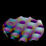
So, once all that stuff is fed into the OSL script, the maths happens. First, it figures out how far away from the centre the calculation’s happening with float Distance = distance(point(0.0,0.0,0.0), P) * Scale; – distance(point1, point2) returns a distance, and we scale that distance with the Scale parameter into the variable Distance.
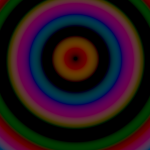
We then perform three fairly similar operations to get our red, green and blue rings: sin(Offset + (Distance * FreqMultiplier) + (FreqMultiplier * TwitchScale * FreqCarrier)) * FreqCarrier;
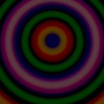
We use an Offset to make sure the factor value stays above zero, then we add together Distance multiplied by FreqMultiplier – the higher the multiplier, the quicker it scales. We then add that to FreqMultiplier multiplied by TwitchScale and FreqCarrier. (FreqCarrier receives FreqInput.) This is the element that makes the rings wiggle back and forth – as the value of FreqCarrier changes with the baked F-Curve, it scales TwitchScale and FreqMultiplier. All of this gets fed into a sine function which creates bands of brightness as the values increase. The quicker the input value increases (thanks to FreqMultiplier), the more bands we get.
(Just so it’s absolutely clear, this combination of variables as well as the actual ring numbers was sheer trial and error on the day. Cycles’ realtime pathtracing mode made them much easier to discover than it would otherwise have been.)
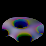
We then multiply the result of the sine function by FreqCarrier so that the bands are brightest at high volume and dark when the F-Curve is at or near 0.0. The reason that we get circular bands from the sine function and not some other shape is that the input to the sine function is being calculated (partly) based off any given position’s distance from a central point. I discovered it’s possible to feed other things into the Po input to warp that relationship to interesting effect – Musgrave noise was pretty spectacular.
Doing this for low, mid and high frequencies, we combine the results together into a single colour at the end with Colour = color(MidFac, HiFac, LoFac); – the high result goes into the green channel, the mid result goes into the red channel and the low result goes into the blue channel.
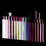
The shader outputs include a colour output as well as separate outputs for each frequency band. (There’s also a couple of testing outputs as well which I don’t really need for a production version.)
Of course, frequency bands are just one possible input. I could bake F-Curves from the overall amplitude of drums, guitar and vocals for the inputs, for instance. Or even kick drum, snare drum and hi-hats if I just wanted to visualise drums.
Anyway. The colour was then given to Emission, the material was applied to a plane which was cameraed exactly from above, I set render samples to 5 and bounces to 1. The frames rendered out in under a second each.
I put the sound and still frames together in Blender’s VSE and rendered it directly out to video from there, and that’s that. 🙂