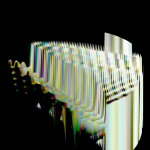
NB: Watch this at the full 720p. YouTube’s compression is making this look a bit ghastly.. or check out still versions here.
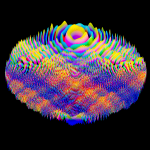
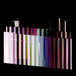
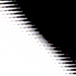
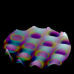
After a full day of rendering, here are some abstract multicoloured waves.
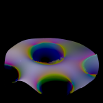
The base geometry is a boring ordinary plane. It hasn’t even been modified by a subdiv surface – it’s that boring.
This is the OSL script in its material:
#include “stdosl.h”
// source: http://glsl.heroku.com/e#12485.1
shader circlees(
float FTime = 1.0,
float Speed = 1.0,
point Po = P,
output color Col = (0.8),
output float Fac = 0.0
)
{
point position = Po;
float SafeSpeed = Speed;
if (SafeSpeed == 0) {
SafeSpeed = 0.000000001;
}
float Time = FTime * SafeSpeed;
float Tcolor = 0.0;
Tcolor += sin( position[0] * cos( Time / 15.0 ) * 80.0 ) + cos( position[1] * cos( Time / 15.0 ) * 10.0 );
Tcolor += sin( position[1] * sin( Time / 10.0 ) * 40.0 ) + cos( position[0] * sin( Time / 25.0 ) * 40.0 );
Tcolor += sin( position[0] * sin( Time / 5.0 ) * 10.0 ) + sin( position[1] * sin( Time / 35.0 ) * 80.0 );
Tcolor *= sin( Time / 10.0 ) * 0.5;
Col = color( Tcolor, Tcolor * 0.5, sin( Tcolor + Time / 3.0 ) * 0.75 );
float red = (position[0] – 0.5)*(position[0] – 0.5) + (position[1] – 0.5)*(position[1] – 0.5) + sin(Time/100.0);
float green = (position[0] – 0.5)*(position[0] – 0.5) + (position[1] – 0.5)*(position[1] – 0.5) + cos(Time/100.0);
float blue = (position[0] – 0.5)*(position[0] – 0.5) + (position[1] – 0.5)*(position[1] – 0.5) + tan(Time/100.0);
Col += color( sin(red*100.0), sin(green * 200.0) , sin(blue * 300.0) );
Fac = (Col[0] + Col[1] + Col[2]) / 3;
}
That OSL shader is fed into a Diffuse and an Emission shader, mixed at 0.5 and fed into the Surface output. The OSL shader is also divided by 0.5 and fed to Displacement. The Experimental mesh Displacement feature was set to True. Subdivision is switched on, Dicing rate is set to 0.002
Speed is set to 0.1, FTime is set to increase by 1 every frame using an FCurve modifier, press render, and 409 frames later, this happens. 🙂